Retour accueil Back to home


The Giant Block-setting Crane super-model n°4, published in 1928, promoted the use of the newly introduced Geared
Roller Bearing (p/n 167). Described on the English leaflet as "The Largest
Meccano Model", it quickly became a symbol of the advanced models that could be
built with Meccano. A long-boom version was used on many manual covers from the 30's
,
then, in 1948, in a curiously mirrored version drawed by Pinyon, and again in
1955 -- even if the GRB
was never to be produced again after the war!
The theme has then often be considered as the ultimate goal for generations of
Meccanomen, and there are few exhibitions where one cannot see several of this
kind of cranes, either based on the super-model leaflet, the manual covers, or
modelled from real-life prototypes.
Even if the Binns Road Model Room did build several samples for promotion
purpose, instructions for the long-boom version have never been issued by
Meccano. Anyway, thanks to some fellow meccanomen, a Modelplan (143) is available at
MW Mail Order since
2003.
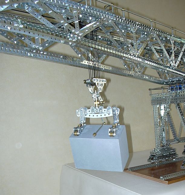
My version above is entirely freelance. Even if it was mainly inspired by the opposite (left) documents, my main constraint was to build an "economic" model -- i.e. with the parts I had in hand at the time. So it "only" needs, beyond the 10-Set contents, some (good stock of) common constructional parts and brassware -- including, to be fair, an additional Bevel pair, two small Helicals, and four 49−holes Flat Girders.
Entirely built from standard parts (motor, R/C control, load and counterweight excepted), the models weights about 32 Kg. The boom is 2.10 m (6' 10") long, or 161 holes (SML 4 is 123 holes long, and the manual cover "long-boom" version is 135), which allow for a total trolley course of 1.12 m (44").
I didn't try to model a real prototype (see References), but kept the manual covers model main proportions, including the too much high base, mainly to stick with the Meccano traditional icon.


The trolley movement is stopped at each end by end-of-course mechanical
clutches. Another end-of-course clutch, still mechanical, prevents
the load to be raised too high.
The load is made from painted wood. The Fidler system, based on the description
in SML 4, is adapted to prevent jamming of the cable.
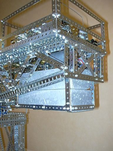
The counterweight is simply made from two painted bricks, fitted in a Meccano
support.

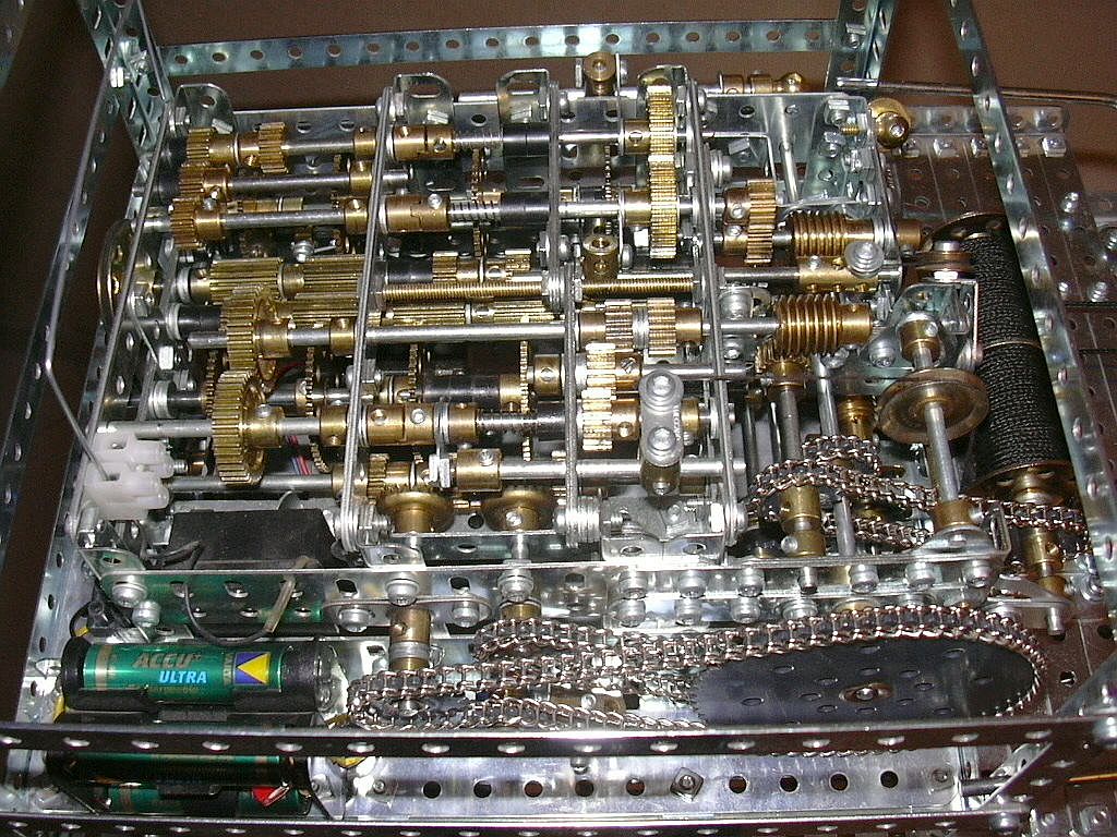
The model is powered by a continuously running single motor (visible on the
counterweight picture above), saved from a car window
winder -- very powerfull and silent.
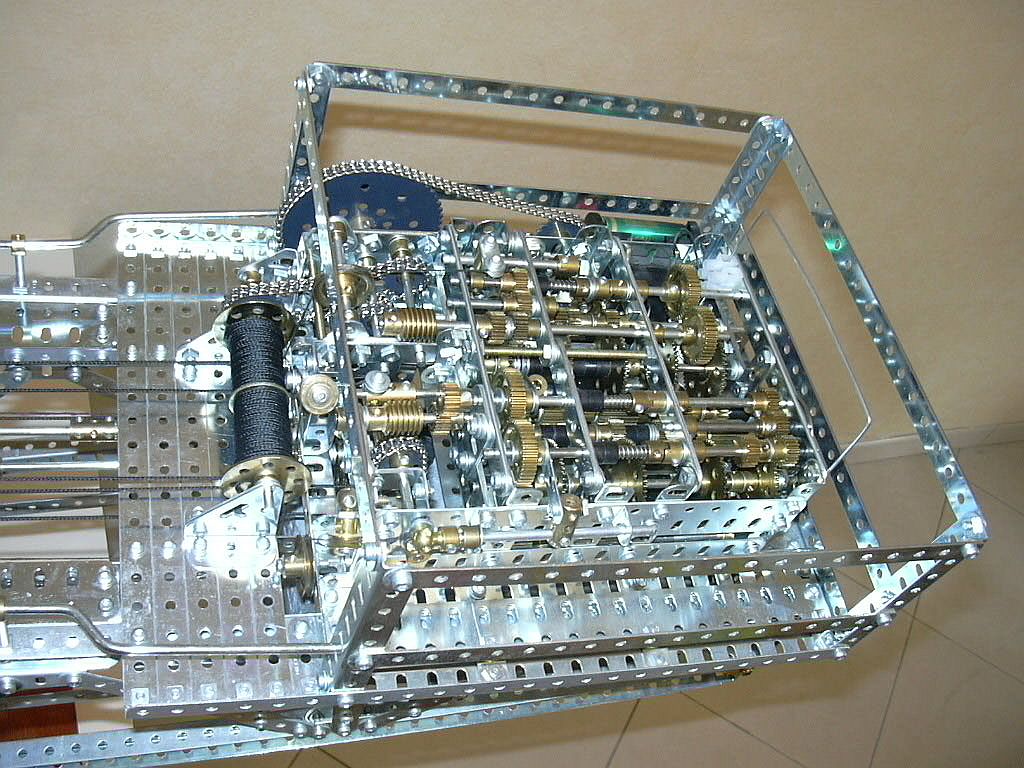
The four movements are driven, one at a time, by a two-way radio-control. The
most complex part of the mechanism is the one allowing, depending of the
positions of the levers (two positions each + neutral, giving a total of 9
combinations), the control of one of the four bidirectional movements (also
giving, including neutral, 9 different possibilities).
Each movement is then transmitted, via the trolley and hoisting end-of-course
clutches, by worms, the latter giving the reduction ratio required and avoiding
the need for brakes.
The gearbox can be removed from the model just by unscrewing four bolts, and
the roof is just clipped. Most of the bearings are made of three stacked
strips, giving precise and silent running, and better lubrification.
The large 3" sproket is an homage to the super-model mechanism.
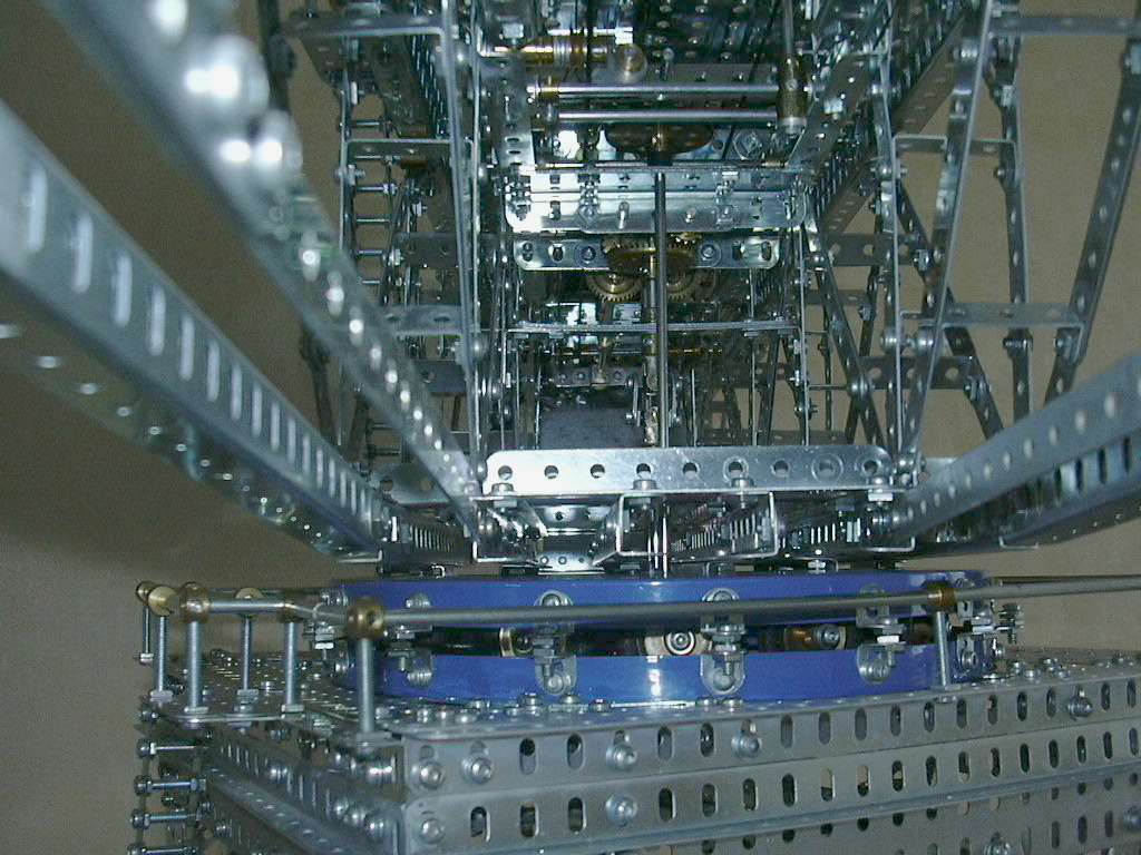
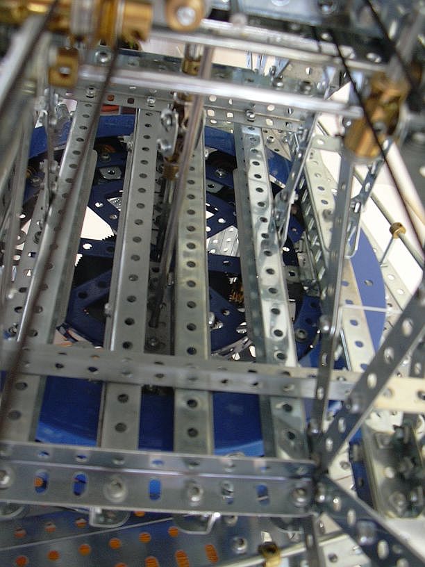
The boom lies on a spider of twelve 1" pulleys with tyres,
sandwiched between two flanged rings fastened to the base. Centering is achived
by a 133 teeth gear wheel, bolted to the base, surrounded by four 19 teeth
pinions, two of them driving the rotation movement. The wheel also acts as a
bearing for the rod transmitting the translation movement.
This gives a smooth running, a better transmission of forces to the base than a
GRB without involving efforts on the central rod -- and preserves the flanged
ring's paint!
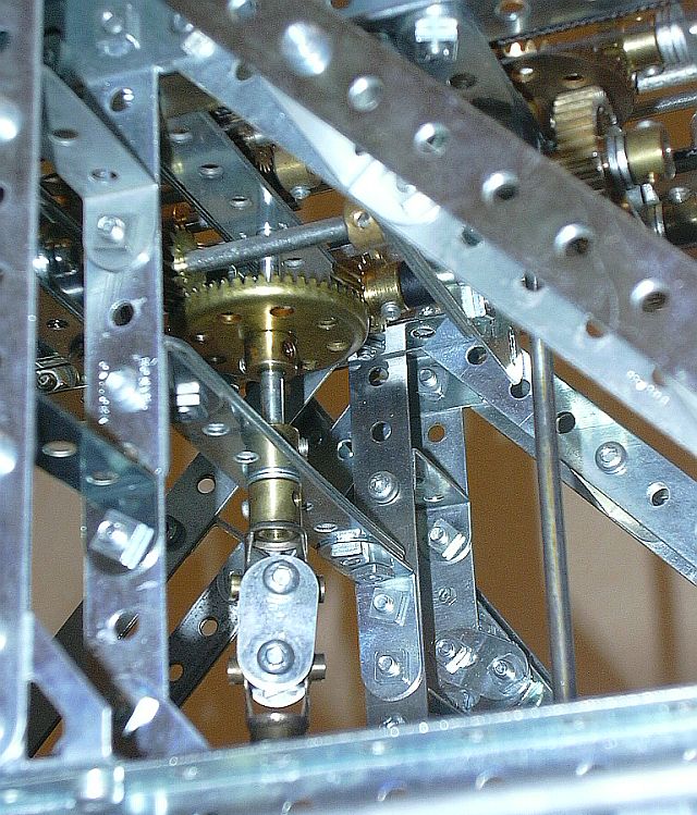
The central mechanism is protected by a roof, removeable just
by unscrewing four bolts.
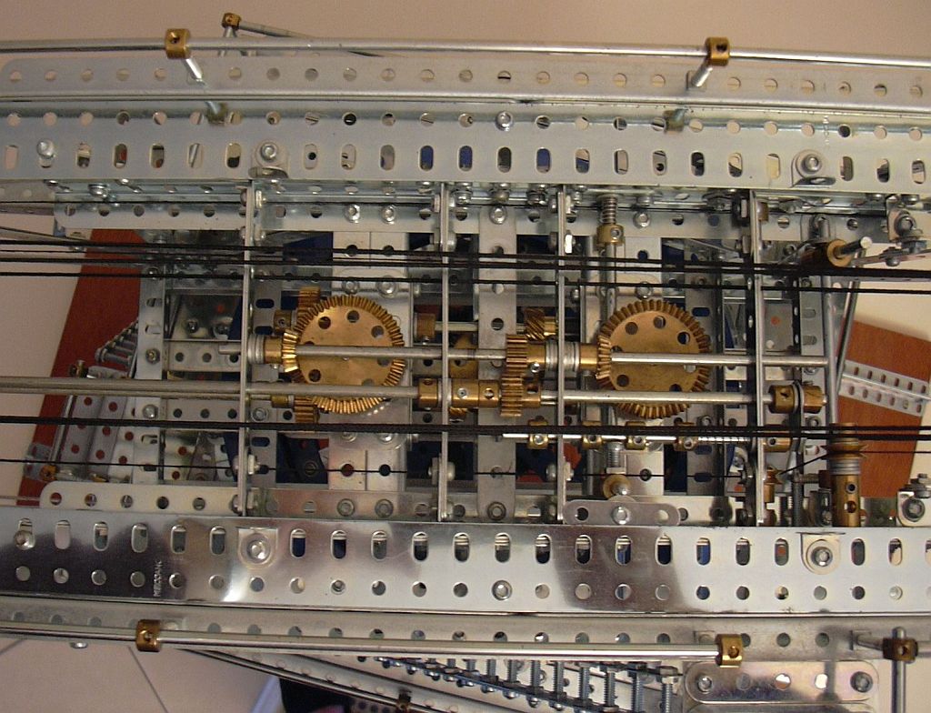
Slewing transmission is done by two bevel gears, which can be manually disengaged
from the main drive by a lever (bottom right on the above picture).
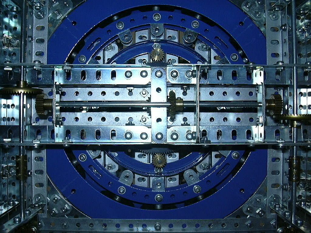
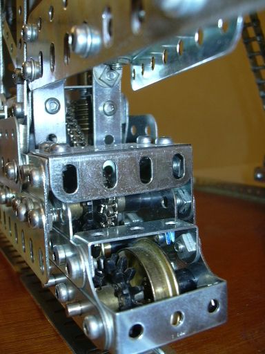
The translation movement is transmitted by small helicals in mesh with a large
contrate -- I've been for a while after an occasion to try this unorthodox
assembly, seen in Bert Love's "Meccano Constructor's Guide". Here two
helicals, diametrally opposed and running in opposite
direction, are needed to balance the high torque and avoid bending of the
contrate's rod. This drive is surprisingly smooth and powerfull.
The contrate's rotation is transmitted to the base by an homocinetical universal
join. The swivels are linked by two pairs of opposite fishplates, the elongated
holes of which allowing for the small length variations due to the oscillations
of the boom.
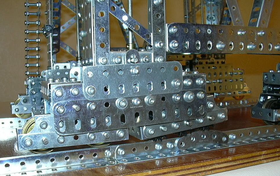
The wheel trains of the somewhat bulky bogies are
articulated twice, once for each pair of axles, and again for adjacent pairs.
This allow for compensation of the running rails irregularities, thus garanteeing correct
adherence for each driving wheel.
Driving is from the inside, in such a way that the intermediate bearings,
colinear to articulation points, do not wear the weight of the model, thus
avoiding additional friction.
Do not miss the excellent Wes Dalefield's pages about his own crane and an extensive bibliography.
See also this interesting Pinyon crane write-up (bottom of page), made for the 2002 exhibition of the Transvaal Meccano Guild.
The splendid Guy Pouchet's crane is really worth a visit.
A few pictures of real-life prototypes can be seen online (other sources welcome):
- Comodoro Rivadavia (Patagonia)
- Comodoro Rivadavia (again)
And several good pictures of real cranes are found in the 1928 Meccano book of ingeneering
